IB182
IB182 - Hydraulic Disconnect Procedure
The original design hydraulic connection requires a special tool to disconnect it. HT-01 is designed for this connection.


Procedure
Insert the fork of tool HT-01 between the sliding sleeve and the flange of the quick connection, Fig. 1. Using the HT-01 push
the sliding sleeve into the slave cylinder connection, Fig. 2. Push the sliding sleeve completely in to the connection. Fig. 3.
The line should disconnect and pop out, CAUTION do not forcefully pull on the line, this will damage the connector.


The new clip style connector, Fig. 5 only requires removing the clip. A small flat screwdriver or needle nose pliers can be
used to remove the clip, and the line will pop out, Fig. 6.


Damaged Connection
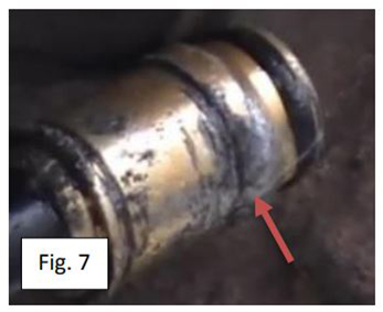
This connector has been damaged by incorrect removal techniques and must be replaced. The connector is designed with a 90 degree shoulder to lock it into the coupling, it has been shaved off from forcefully pulling it out of the coupling. The line from the master cylinder must now be replaced.


Compatible Connections
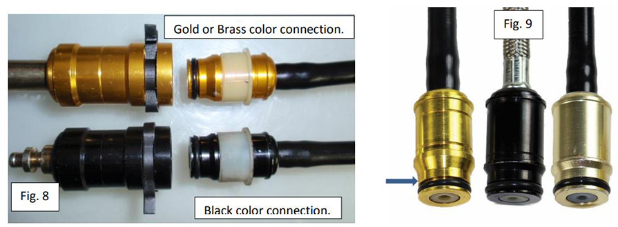
Two similar designs have been used, the early connection system was a black color and the later system is a gold or brass color. See Fig. 8.
PLEASE NOTE: these connections are not interchangeable and can only be used in sets. They have different dimensions.
Any attempt to install a gold to a black coupler on a vehicle indicates that a component has been incorrectly replaced and does not represent a catalog error.


Fig. 9 L-R shows a gold or brass color, black color and a non-standard color produced by an aftermarket supplier. By color the one on the right is not gold or brass but by dimensions and profile it is the black connection. The manufacturer has not maintained the precedent of the gold or brass color vs. black to provide visual confirmation. The sleeves were removed to aid in illustrating the color of the plug.
Fig. 9 the blue arrow, this dimension is .590” for the gold and .610” for the black plug.
Our products maintain the original gold/brass vs black color to help identify these different connectors and couplers.
PLEASE REFER TO FACTORY SERVICE MANUALS FOR DETAILED APPLICATION SPECIFIC PROCEDURES.
This bulletin is to assist in the safe and effective servicing of this application. Transmissions, transaxles and transfer cases are heavy and their safe removal and replacement requires the use of proper tools, equipment and procedures to prevent injury and damage. Always read and follow instruction bulletins and factory service manuals for detailed clutch servicing procedures.
Bulletins and any additional information: www.clutchtechsupport.com
IB182
03/05/2019


