
IB198
Pressure Plate to Flywheel and Clutch Release Fork Installation
BALANCE MATCHING
Prior to removing the clutch, locate the white "X" on the flywheel. It may be necessary to rotate the flywheel to locate the "X". This new clutch cover has the light side marked with a paint daub or dot during the balancing process. This mark is to be aligned with the white "X" on the flywheel during the installation process. See Figure 1 below.

CLUTCH FORK INSTALLATION
This application is a pull type clutch. The clutch fork ears must be in the fork groove, not behind the bearing. The fork can be clipped in place as shown in Figure 2 to install the transmission, and then pushed into position as shown in Figures 4 thru 6.
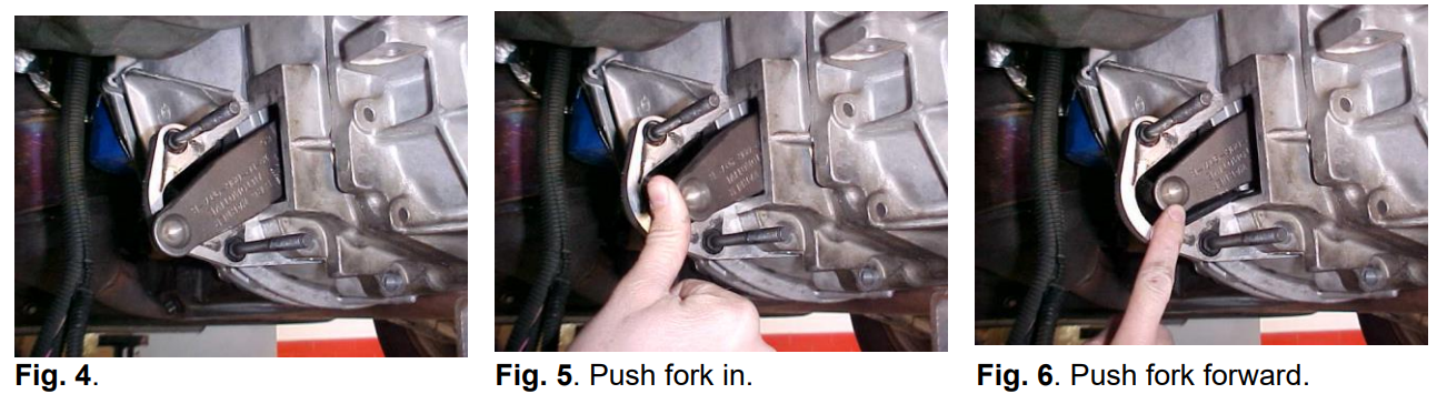
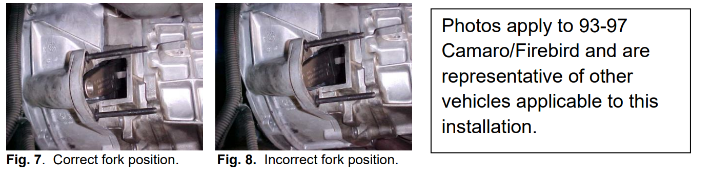
The fork ears must be positioned in the bearing fork groove, not behind the bearing. This can be confirmed by looking into the clutch housing and verifying the fork position. Figure 7 shows the fork in the correct position.
Note: This flywheel is externally balanced and has a cast in counterweight. If the white "X" is not found, it is in the same area as the cast in counterweight on the engine side of the flywheel.
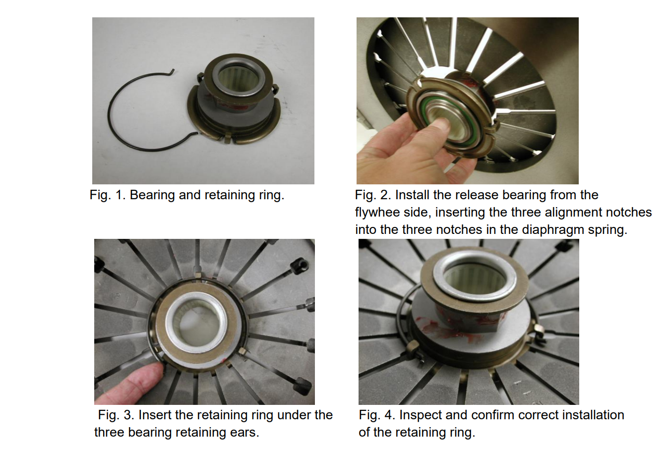
Release Bearing Installation
PLEASE REFER TO FACTORY SERVICE MANUALS FOR DETAILED APPLICATION SPECIFIC PROCEDURES.
This bulletin is to assist in the safe and effective servicing of this application. Transmissions, transaxles and transfer cases are heavy and their safe removal and replacement requires the use of proper tools, equipment and procedures to prevent injury and damage. Always read and follow instruction bulletins and factory manuals for detailed clutch servicing procedures.
Bulletins and any additional information:
IB198 06/25/2015