
IB230
Clutch Servicing Instructions
Installation of this unitized clutch system requires using the original adaptor plate to crankshaft bolts, adaptor plate bolt reinforcement ring and adaptor plate to flywheel bolt as illustrated below. If the system being replaced is not the original Dodge Dual Mass Flywheel system, then these parts will be required. Contact a Dodge or Ram dealer for these parts.
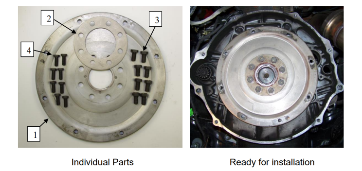
To inspect for the Adaptor Plate, remove the inspection plate on the engine to transmission housing and the adaptor plate can be seen in the top hole. This access hole is used to remove the adapor plate to flywheel bolts.
Dodge or Ram part numbers as of 2013:
- Ref 1. Qty. 1. Plate, Adaptor. 52104720-AE
- Ref 2. Qty. 1. Plate, Washer. 4798968
- Ref 3. Qty. 8. Bolt, Hex. 5085962-AA
- Ref 4. Qty. 8. Bolt, Hex. 6508033-AA
Dodge 5.9L and 6.7L Disel with G56 Transmission
WARNING: PLEASE READ THIS INSTRUCTION BULLETIN PRIOR TO REMOVING THE TRANSMISSION OR CLUTCH ASSEMBLY. THIS CLUTCH SET WILL REPLACE THE DUAL MASS FLYWHEEL (DMF) AS AN ASSEMBLY. DO NOT DISASSEMBLE THE UNITIZED CLUTCH SYSTEM.
- Prepare the transmission for removal, but DO NOT remove the transmission.
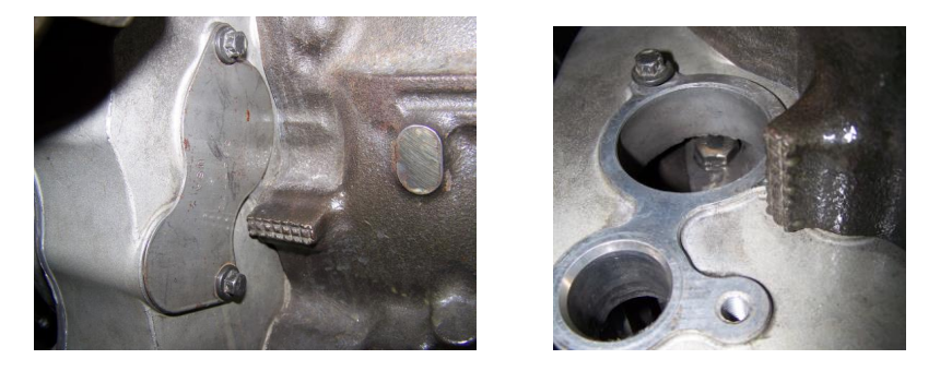
- Locate the cover plate on the passenger side of the engine to transmission adaptor. This plate is behind the turbo and is a figure 8 shape. This cover plate is attached with 2 hex bolts, remove the cover plate, refer to Figure 1 and 2.
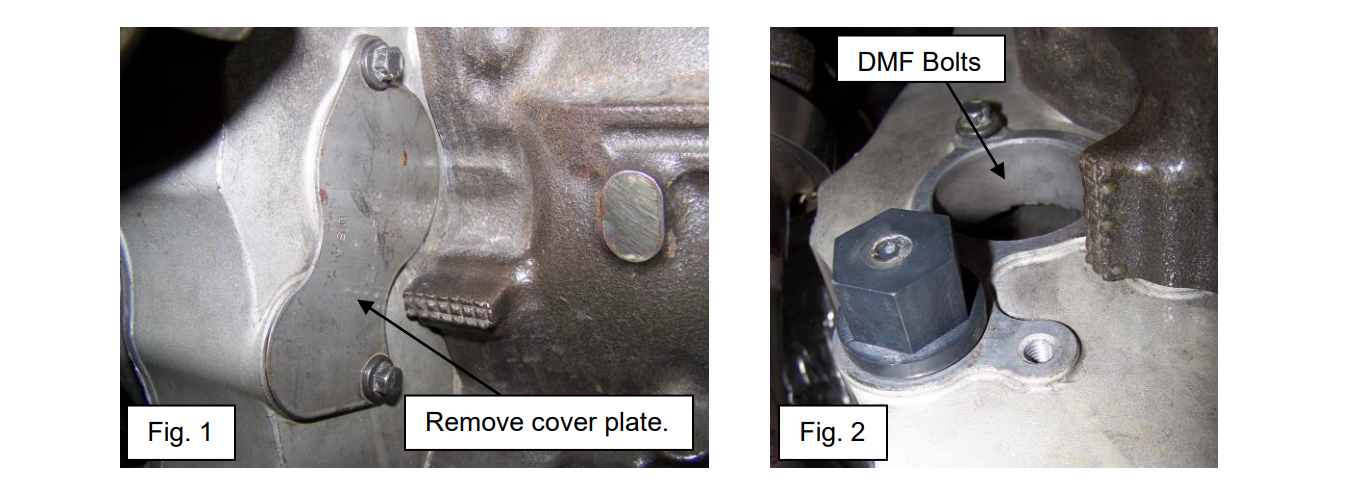
3. Firmly insert the engine Barring Tool in the bottom hole, refer to Figure 2. The teeth on the tool will engage the ring gear and will be used to rotate the engine. Using a 1 1/8" socket and suitable extensions rotate the Barring Tool clockwise with a hand ratchet until one of the DMF to flex plate bolts is located in the center of the top hole.
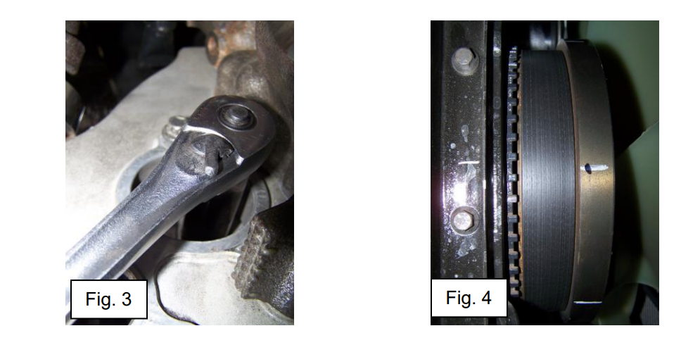
4. Remove the DMF to flexplate bolt, refer to Figure 3. See bolt warning, bottom of page 4.
5. We recommend marking the crankshaft damper to the oil pan to identify the crankshaft position for this bolt location, see Figure 4. WARNING: Do not mark on or damage the teeth of the crankshaft position tone ring.
6. Using the Barring Tool rotate the engine to the next DMF to flexplate bolt, remove the bolt, mark the position and continue the process to remove all 8 DMF to flexplate bolts.
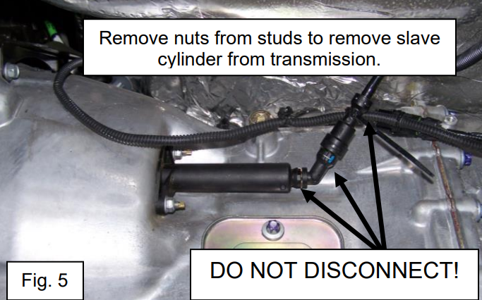
7. CAUTION: DO NOT REMOVE THE LINE FROM THE SLAVE CYLINDER. See Figure 5. Remove the slave cylinder by unbolting it from the transmission and secure it out of the way of transmission removal.
8. Remvoe the transmission. CAUTION: At this point the entire DMF and clutch assembly will be on the input shaft of the transmission, do not allow the transmission to tolt forward.
9. The following is recommended as a two person job, see Figure 5. Thread the two 10mm bolts supplied with the Unitized Clutch assembly into two of the DMF to flexplate holes (10 o'clock and 2 o'clock recommended) carefully pull the DMF and clutch assembly off as an entire unit. Place the assembly on a suitable bench or cart. CAUTION: This assembly is heavy (100 lbs) and personal injury may result from incorrect handling. If the vehicle is four wheel drive with transfer case attached it is recommended to support the transfer case during steps 10 thru 15.
10. Remove the release bearing, clean and inspect the guide tube, inspect the clutch release fork noting its orientation. Apply grease as needed to fill the release bearing grease groove. Apply a light film of grease to the guide tube. Do not over lubricate.
11. Lightly grease the release bearing fork ears. Install the fork and new release bearing.
12. Thoroughly clean and then apply a very light film of spline grease to the input shaft splines, the disc spline has a light film of grease already applied.
13. Using the bolts from step 10, thread the bolts in the Unitized Clutch flywheel as in step 9.
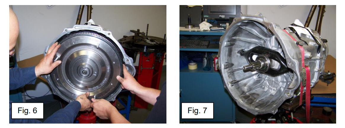
14. The following is recommended as a two person job, see Fig. 6. Carefully lift the new Unitized Clutch and slide it onto the input shaft as an assembly. Maintain a slight (engine side) upward angle to the transmission as the transmission is handled and positioned. When the Unitized Clutch is fully inserted on the input shaft, the pilot bearing section of the input shaft will extend through the pilot bearing.
15. Inspect the dowel sleeves and dowel sleeve pilot holes on the engine and transmission, clean and then lubricate with a light film of grease. Clean and inspect the flywheel pilot
hole in the crankshaft and the pilot of the Unitized Clutch assembly, lubricate with a light film of grease.
16. Carefully position the transmission, raise it into position and slide the transmission forward on to the dowel sleeves and flywheel to crankshaft pilot hole, secure the transmission with the mounting bolts, torque to specification.
17. Push the release fork towards the engine. This seats the flywheel into the crank pilot.
18. Carefully rotate the Unitized Clutch into position until the first bolt hole is located, install the bolt, and tighten until snug. NOTE: The bolts will later be tightened in a two step
process. Using the Barring Tool, rotate the engine until the next bolt hole appears, install the bolt, and repeat the process until all 8 bolts have been installed.
19. Using the Barring Tool, rotate the engine and torque all 8 bolts to 20 lb/ft, continue rotating and tightened to a final torque of 45 lb/ft for all 8 bolts.
20. Remove the engine Barring Tool and install the cover plate removed in step 2.
21. Complete the installation.
HYDRAULIC RELEASE SYSTEM
As a maintenance item while the slave cylinder is removed from the transmission, the following steps can help remove trapped air in the release system.
1. With the slave cylinder connected to the hydraulic line.
2. Slave cylinder removed from the transmission, push rod end pointed slightly down.
3. Remove the cap and bellows from the master cylinder reservoir.
4. Slowly push the slave cylinder pushrod firmly into the slave cylinder body. Do not push fast as this may squirt DOT 3 onto body components.
5. Allow the pushrod to return to its extended position.
6. Repeat several times.
7. If air bubbles are noticed in the fluid, this is an indication that the system has air in it and additional bleeding is required.
8. Adjust fluid level in clutch master cylinder reservoir.
The clutch requires a full release stroke and any trapped air reduces the total available release stroke, resulting in difficult clutch release and selection of 1st or Reverse.
PLEASE REFER TO FACTORY SERVICE MANUALS FOR DETAILED APPLICATION SPECIFIC PROCEDURES.
This bulletin is to assist in the safe and effective servicing of this application. Transmissions, transaxles and transfer cases are heavy and their safe removal and replacement requires the use of proper tools, equipment and procedures to prevent injury and damage. Always read and follow instruction bulletins and factory service manuals for detailed clutch servicing procedures.
Bulletins and any additional information:
IB230 06/25/2015